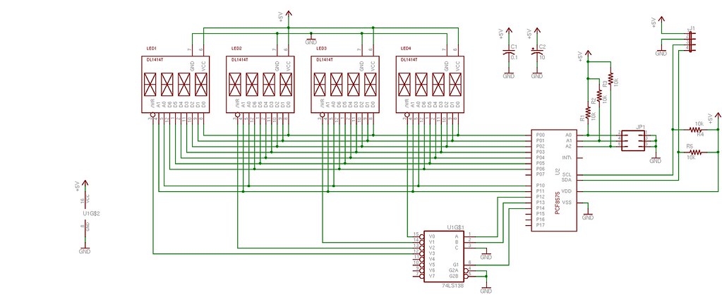
So while these old-fashioned displays are definitely not something for new projects, I still like using them when I play around with Arduinos and such, for nostalgic reasons if nothing else. In my post on this topic years ago, I had used a few DL1414 alphanumeric displays for my first "Hello, World" AVR program. While they worked well for that purpose, they are are bit of a pain to wire up for experimenting, especially when you want more than four characters with some of the lower pin-count devices. So I took that design (with the 3:8 decoder) and added a PCF8575 I2C I/O expander chip so that the displays can be connected to an AVR or Arduino only using two I2C pins. I briefly thought about using a shift register approach, but while it helps reduce the number of lines required for data and addressing, additional logic would still be required to drive the R/W pins of the display. Furthermore, while I haven't thought about it much, I believe it would require more complex programming on the microcontroller as well. I like the simplicity of the I2C approach and the fact the display could sit on the same I2C bus as other peripherals.
The PCF8575 has 16 digital I/O pins, grouped into two ports of 8-bits each. Data is sent to the '8575 in the normal fashion with I2C in groups of two bytes. The "P0" port is the first byte of data, the "P1" port is the second. In this design the '8575 is used strictly as an output device and no pins are read (used as inputs). I assigned P0 to the D0-D7 on the displays, thus the first byte of data sent (P0) is the ASCII character displayed. In order to control which character position is written to, lines P11 and P10 are tied to A1 and A0 of the displays and P13 and P12 drive the two lower bits of a 74138 TTL 3:8 decoder. The 3:8 decoder in turn drives the R/W signal of each display. (Only two bits are needed since there are only four displays.) With this design, the lower 4 bits of the P1 port can be used to address each of the 16 individual characters that make up the display. One last line, P14 is used to drive an enable signal of the 3:8 decoder and becomes the R/W signal for the entire display.
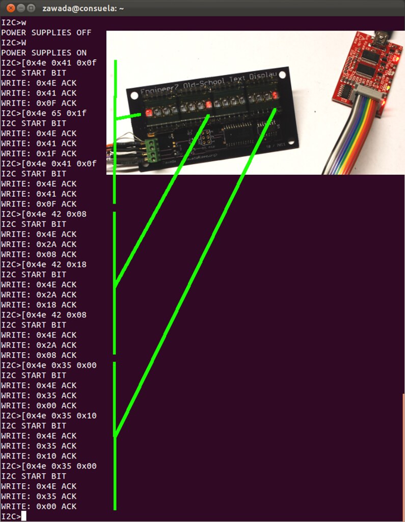
The only thing I don't like about this approach is the clunky way that six bytes of data need to be sent for each character displayed. The character and address data is first sent without the R/W bit set in order to prepare the display inputs without actually writing the data. The data is sent again with the R/W bit (P14) set 'high' to strobe the ASCII data into the selected character and make it appear. Finally, the data is sent one last time with the R/W set low again so that the display module no longer reads the inputs. It's necessary to do this in three steps because trying to write the data and/or address at the same time the R/W is active yields unpredictable results. The only way to make sure the character shows up in the right position is to make sure the data and address lines are held constant while the R/W bit is strobed. Note that P14 is actually active 'high' which is actually opposite of the actual display R/W in which is active 'low'. This gets taken care of by the 3:8 decoder which has active 'low' outputs.
The only thing I don't like about this approach is the clunky way that six bytes of data need to be sent for each character displayed. The character and address data is first sent without the R/W bit set in order to prepare the display inputs without actually writing the data. The data is sent again with the R/W bit (P14) set 'high' to strobe the ASCII data into the selected character and make it appear. Finally, the data is sent one last time with the R/W set low again so that the display module no longer reads the inputs. It's necessary to do this in three steps because trying to write the data and/or address at the same time the R/W is active yields unpredictable results. The only way to make sure the character shows up in the right position is to make sure the data and address lines are held constant while the R/W bit is strobed. Note that P14 is actually active 'high' which is actually opposite of the actual display R/W in which is active 'low'. This gets taken care of by the 3:8 decoder which has active 'low' outputs.
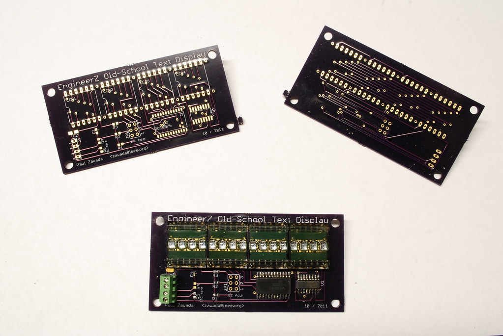
After I designed the boards in Eagle last winter, the project sat idle for the better part of the year. Finally, a few weeks ago I decided to finish it off and sent the gerber files off to the Dorkbot PDX PCB service. In a couple of weeks I had three beautiful boards back for under $30. Though it wasn't the first time I've had PCBs fabricated, it was the first time I had used Laen's service and I am very pleased - I highly recommend it.
So finally, a couple of weeks ago the moment arrived and I hand-assembled one of the boards using the few necessary parts in less than an hour. Other than the displays themselves, the design is mostly surface mount. (Admittedly there is a bit of irony in using 0603 SMT resistors and SOIC chips to drive early-1980s display technology.) Once assembled, I tested the board using my Bus Pirate. Given the simplicity of the design, it was very easy to light up the display. By simply sending three commands per character, I was successfully able to make characters appear on the display - success!
While I was able to send a character or two to the display with the bus pirate, it quickly became apparent that sending anything more than a few characters was very cumbersome. So I whipped up a short Arduino sketch to display a string. If I start using the display quite a bit, I'll probably turn the program into a library. However I'm holding off for now because haven't decided what the best way to structure it is and what functions I would want to include beyond displaying a character or a string of characters. It would also be nice to have a function for a scrolling display for strings longer than the display width. Ideally such a function would work in conjunction with a timer-driven interrupt routine so the main Arduino loop can be free to take on whatever function it's intended to perform.
All of the Eagle files and sample code can be found in my Old School Text Display GitHub repository. I'd be shocked if many people are interested in the files, but they are out there if you want them!


1 comment:
Dude! Get back on your meds! ;-)
Awesome job. ;-). Kb8cne
Post a Comment