Sunday, December 11, 2011

Alphanumeric LED Displays Revisited

As I noted when I first started playing with AVR microcontrollers a few years ago, I've always really liked alphanumeric LED displays.  This probably because I used them when I first started programming 68HC11 micro controllers in the late '80s.  There wasn't much else available at the time.  LCDs tended to be highly customized (no ubiquitous 16x2 character displays back then!) and VFDs were expensive, required LSI chips to drive them and required a high-voltage power supply.  (Again drop-in modules weren't widely available...)  These alphanumeric LEDs weren't exactly cheap, but they were well within reach of a college student's budget and abilities.

So while these old-fashioned displays are definitely not something for new projects, I still like using them when I play around with Arduinos and such, for nostalgic reasons if nothing else.  In my post on this topic years ago, I had used a few DL1414 alphanumeric displays for my first "Hello, World" AVR program.   While they worked well for that purpose, they are are bit of a pain to wire up for experimenting, especially when you want more than four characters with some of the lower pin-count devices.  So I took that design (with the 3:8 decoder) and added a PCF8575 I2C I/O expander chip so that the displays can be connected to an AVR or Arduino only using two I2C pins.  I briefly thought about using a shift register approach, but while it helps reduce the number of lines required for data and addressing, additional logic would still be required to drive the R/W pins of the display.  Furthermore, while I haven't thought about it much, I believe it would require more complex programming on the microcontroller as well.  I like the simplicity of the I2C approach and the fact the display could sit on the same I2C bus as other peripherals.


The PCF8575 has 16 digital I/O pins, grouped into two ports of 8-bits each.  Data is sent to the '8575 in the normal fashion with I2C in groups of two bytes.   The "P0" port is the first byte of data, the "P1" port is the second.  In this design the '8575 is used strictly as an output device and no pins are read (used as inputs).  I assigned P0 to the D0-D7 on the displays, thus the first byte of data sent (P0) is the ASCII character displayed.  In order to control which character position is written to, lines P11 and P10 are tied to A1 and A0 of the displays and P13 and P12 drive the two lower bits of a 74138 TTL 3:8 decoder.  The 3:8 decoder in turn drives the R/W signal of each display.  (Only two bits are needed since there are only four displays.)  With this design, the lower 4 bits of the P1 port can be used to address each of the 16 individual characters that make up the display.  One last line, P14 is used to drive an enable signal of the 3:8 decoder and becomes the R/W signal for the entire display.


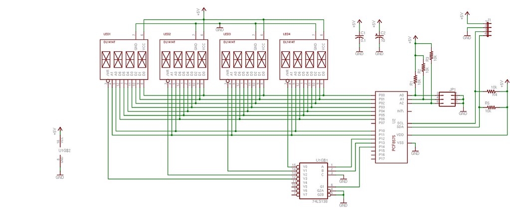
The only thing I don't like about this approach is the clunky way that six bytes of data need to be sent for each character displayed.  The character and address data is first sent without the R/W bit set in order to prepare the display inputs without actually writing the data.  The data is sent again with the R/W bit (P14) set 'high' to strobe the ASCII data into the selected character and make it appear.  Finally, the data is sent one last time with the R/W set low again so that the display module no longer reads the inputs.  It's necessary to do this in three steps because trying to write the data and/or address at the same time the R/W is active yields unpredictable results.   The only way to make sure the character shows up in the right position is to make sure the data and address lines are held constant while the R/W bit is strobed.  Note that P14 is actually active 'high' which is actually opposite of the actual display R/W in which is active 'low'.  This gets taken care of by the 3:8 decoder which has active 'low' outputs.

After I designed the boards in Eagle last winter, the project sat idle for the better part of the year.  Finally, a few weeks ago I decided to finish it off and sent the gerber files off to the Dorkbot PDX PCB service.  In a couple of weeks I had three beautiful boards back for under $30.  Though it wasn't the first time I've had PCBs fabricated, it was the first time I had used Laen's service and I am very pleased - I highly recommend it.

Display Boards


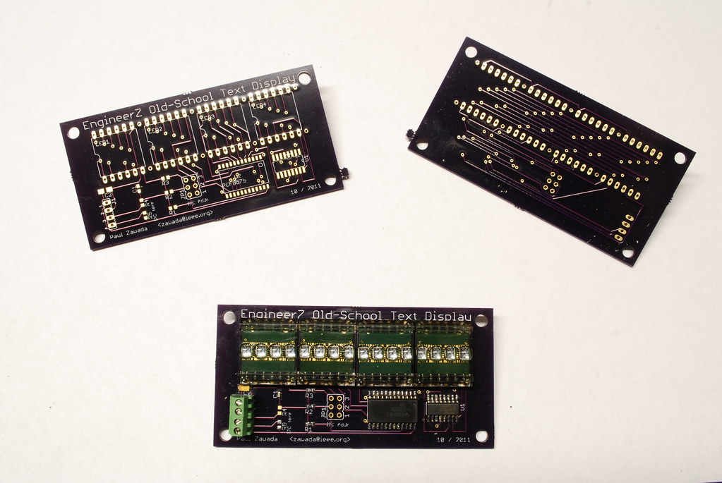
So finally, a couple of weeks ago the moment arrived and I hand-assembled one of the boards using the few necessary parts in less than an hour.  Other than the displays themselves, the design is mostly surface mount.  (Admittedly there is a bit of irony in using 0603 SMT resistors and SOIC chips to drive early-1980s display technology.)  Once assembled, I tested the board using my Bus Pirate.  Given the simplicity of the design, it was very easy to light up the display.  By simply sending three commands per character, I was successfully able to make characters appear on the display - success!

display-bus-pirate


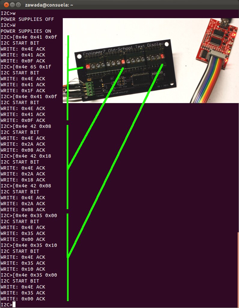
While I was able to send a character or two to the display with the bus pirate, it quickly became apparent that sending anything more than a few characters was very cumbersome.  So I whipped up a short Arduino sketch to display a string.   If I start using the display quite a bit, I'll probably turn the program into a library.  However I'm holding off for now because haven't decided what the best way to structure it is and what functions I would want to include beyond displaying a character or a string of characters.  It would also be nice to have a function for a scrolling display for strings longer than the display width.   Ideally such a function would work in conjunction with a timer-driven interrupt routine so the main Arduino loop can be free to take on whatever function it's intended to perform.

Old School Text Display

All of the Eagle files and sample code can be found in my Old School Text Display GitHub repository.  I'd be shocked if many people are interested in the files, but they are out there if you want them!

Saturday, February 26, 2011

PWM on the AVR ATTiny2313

Pulse width modulation (PWM) can be used for a wide variety of things: controlling motor speed, synthesizing sounds, dimming LEDs by varying amounts, even amplifying signals.  In a nutshell, you take a train of pulses and vary the duty cycle (percentage of time on vs off) to control the output of your target device, which could be a spinning rotor or a speaker cone.   Usually some filter effect comes into play, whether it be a tuned L-C circuit placed in front of the speaker or the rotational inertia of a motor.  The great thing about PWM is that it is usually very power-efficient.

Lately, I've been playing with the PWM channels on the ATTiny2313 AVR microcontroller.  PWM on the AVR looks pretty daunting when you first start looking at the data sheets, but it's actually pretty straightforward.  The best thing about the PWM channels on the AVR is that they are implemented completely in hardware, meaning that the PWM doesn't need any software to run, not even an interrupt service routine.  All you have to do is set a few registers and it's generating a signal!  It can get more complicated than that if you want take advantage of the number of options available, butyou can keep things pretty simple if you want.

PWM is based on the AVR hardware timer.  The timer is a counter that is automatically incremented by the microprocessor clock through a configurable divider.  The timer can be configured to send an interrupt request every time it overflows, making it a way to run code on a periodic basis.  But besides that, the PWM hardware also allows the timer to send an output signal via one of the AVR's output pins.  So if we can figure out how to reset that output after some amount of time, the AVR can send a pulse on a periodic basis.  This is where PWM comes in...  We can configure the AVR to reset the signal at value of the timer before it overflows.   This value will determine the duty cycle of our signal.

For example, if our timer uses an 8-bit coutner, it will continuously count from 0 to 255.  Every time it hits 255 it will reset to 0 and start over, sending an interrupt request if we choose.  At that point it can also raise an output to a logic high state.  We can also set a PWM register so that when the counter reaches some intermediate number, lets say 128, it resets the output to a logic low.   So as the timer continuously counts, the output will toggle up and down producing a square wave.  In this example square wave will have a 50% duty cylcle (128 is 50% of 256)...  If we set the PWM control register to 64, the duty cycle will be 25%.

Those are the basics of how PWM works on the AVR microcontroller...  There are a couple of really good tutorials at the AVRFreaks web site that cover PWM in depth; here's one for example.  (You'll need to get a free account to get to a lot of the good information on the AVRFreaks web site.)

For a demo, I set up an ATTiny2313 with its OC0A output driving a N-channel MOSFET to switch a load off and on.  OC0A is a PWM output based on the 8-bit timer 0 of the ATTiny2313.  In this case, I'm driving a 30 mA meter movement I bought at a hamfest last fall.  In series with the meter movement and MOSFET is a 1 kΩ  trimmer pot that I set so that the meter reads full scale when the OC0A output has a 100% duty cycle (constant logic high.)  The meter will read a value proportional to the duty cycle of the OC0A PWM output.  So when the OCRA0 register is set to 128, the meter will read 15 mA.


To make the demo interesting, I used Timer 0 to update the PWM duty cycle every second.   The default clock configuration on the ATTiny2313 causes timer 0 overflow interrupts 3906 times a second - way more often than I want to update the PWM duty cycle.  To slow things down, I use the timer overflow interrupt service routine to increment a clock scaling counter and watch that counter in the main loop of the program.  When that counter hits 3906, I update the PWM duty cycle and clear the counter.  As for the actual duty cycles I display on the meter, I start at 0 and increment the duty cycle 1.6% each time.  After 60 seconds, the duty cycle reaches 100%, the meter reaches full scale, and  I set the duty cycle back to zero.   My sample code is over here in GitHub.  Below is a video of the demo setup.

Sunday, January 23, 2011

DS1307 Tinkering

A couple of weeks ago I finally had a chance to assemble the Adafruit DS1307 Breakout Board I bought awhile back.  The DS1307 is a popular real-time clock that communicates with an I2C interface.  The Adafruit board is a really simple kit - the DS1307 itself, a timing crystal, a bypass capacitor, a couple of pull-up resistors for the I2C bus, and backup coin cell.


Once I got the board assembled, I started to interrogate the DS1307 with my Bus Pirate (another recent purchase).  The Bus Pirate is a great tool for testing and experimenting with new hardware.  In a nutshell, it's a device that connects your computer's USB to a variety of common interfaces like I2C, SPI, 1-Wire, etc.  Using the Bus Pirate's command-line interface, one can quickly evaluate a device by sending the appropriate bit patterns and monitoring the response.  There's a bunch of tutorials for the the Bus Pirate at the Dangerous Prototypes web site, including one for the DS1307.  Loosely following that tutorial I quickly verified that my DS1307 was working.


Once I verified the device worked, I wrote a quick and dirty Arduino program to display the time.  My plan was to use the Arduino to directly drive a four-digit seven-segment display I had in my junk box.  I used seven digital outputs for the segments and four additional digitals for each digits common cathode.  Using a timer interrupt routine, the display digits are scanned by setting segment bits high and one of the digit CC lines low every time the timer overflow interrupt fires.  (The source code is over here at github.)


While the display worked, I was disappointed by how dim it appeared.  I slowed down the scan rate by putting a counter dividing variable in the timer ISR, but that didn't help.  It looked dim even when I slowed down the scan rate to 1 second per digit.  (Obviously the scan flicker at that rate is exaggerated, but I wanted to see what effect the scan rate had on the dimness.)   So thinking dimness might be due to the Arduino's inability to source or sink enough current to light the display brightly, I added some driver transistors to the circuit to drive the LEDs from an external power supply.  (Schematic below.) That didn't help either, so for now I'll chalk it up to the display itself and its lack of contrast under my shop light and lack of red filter.  However, the LED segments do seem to glow a little brighter when tested with a power supply, so the transistor approach probably could be made to drive the LED brighter.  But that's for another day...

Saturday, January 15, 2011

Blog Relaunch: PowerBook Surgery

When I started Facebooking and Twittering, the activity on my blog went from little to none.   I hadn't touched it in a couple of years and the Movable Type installation was woefully out of date.  At the same time, the open source hardware movement has inspired me to try to contribute a little here or there...  So I moved the technology-related postings from the past to a new platform (that I don't have to maintain) and decided to start posting bits here and there on what I've been up to in the workshop.

The most recent activity on the bench was major surgery on my laptop.  Now mind you, my laptop is a 6+ year-old Apple PowerBook (PB) G4, so when the power jack got worn out, I thought this would be a good reason to finally upgrade to a shiny new MacBook pro.  However, given my wife's desire for new windows on our home and her quickness to remind me about the Self-Repair Manifesto poster in my workshop, I decided it would be best to take a crack at fixing the laptop myself.   After all, we do have a relatively new iMac in the house, so I have access to a faster machine.  The PB is still perfectly good for development tools like gcc and Eagle (and I don't have to share it), so it's definitely useful for me to keep it around.

First, here are a couple of photos of what I was replacing.  The Apple "Magsafe" connector didn't show up until the MacBook.  What they used on the PowerBook is a modified 3.5 mm phono plug.  The shroud that surrounds it keeps you from plugging it into a regular audio jack and serves as a connection for the green/yellow LED in the plug.  I believe jack/plug combo was failing because their contacts get pitted over time from the arcing that occurs from plugging in an energized power adapter.  Over time, the pitting itself makes the arcing more apt to occur and the problem snowballs.  (More arcing -> more pitting -> more arcing...)  It's difficult to see in the photo, but there are whole pieces of the ring and sleeve missing in the plug.  There are a few spots where only the plastic insulator that sits inside the connector remains.


As noted in a previous post, I have torn my laptop open before using the iFixit Repair Guide.  Once again, their information did a wonderful of guiding me through the process of removing the almost 5000 screws that hold the laptop together.  After about 30 minutes, I got down to the DC input board which is buried under just about everything else, including the motherboard:


Now, before I started this endeavor, I Googled a bit to see if anyone had posted any on doing a similar repair.  I found an blog article where someone replaced the original power jack on a 15-in PB with a standard coaxial DC power jack, which is exactly what I planned to do.  So while I had some guidance, I am glad I did some investigation on my own before blindly following those directions.  What I found was that the polarity marking in the photos did not match what I found by checking continuity and voltages on my own.  (Luckily, the connection between my jack and plug was still working enough so I could measure the voltages on the jack.)  The 15" PB power jack mounted with a different PCB arrangement than the 12" PB, so it's quite possible Apple used a jack on the 12" PB that had a completely different footprint.  Either that, or the guy who wrote the article marked his photo wrong.  Either way, I'm glad I checked things out before smoking my PB's DC-to-DC converter. 

After I removed the DC input board, I did a test fit of the new coaxial jack.  Once I verified everything would fit, I carefully removed the old jack from the PCB:


Then I prepared the new jack with some sort wires and heat shrink tubing.  (Note the PB's insides scattered all over my bench...)

Finally, I reinstalled the PCB and put the machine back together:


As you can see, the PB worked when I put it back together.  It actually took two tries; the first time I put it together, the display had no raster.  I opened it back up and reseated the video cable and success!  I am happy to report that the power adapter works and charges the battery as well.  I guess I have to come up with another excuse to buy that MacBook Pro...

One last note: In the article I cited above, there is a discussion in the notes about a sensing voltage set by a resistor connected to the tip of the original plug.  I decided to leave it out since I only have a 45 W adaptier.  Without seeing the sensing voltage, the PB charges at the slowest rate.  (At least that seems to be the consensus in the article comments.)  I've kept an eye on the power adapter and it doesn't seem to be heating up, so I think I'm safe.